Quality Management
Power Function Graphs
James O. Westgard, Ph.D.
Power Function Graphs are statistical tools. They reveal the performance of the statistical rules used in the laboratory. Why do those 12s rules have so many repeat runs? One power function graph will explain it to you.
- How do you evaluate the performance of a QC procedure?
- What are the critical QC performance characteristics?
- What is a power function graph?
- How do you use a power function graph?
- How are power curves determined?
- How do you read a Validator power function graph?
- How do false rejection and error detection depend on control limits?
- Where can you obtain power function graphs?
- References
If I were to ask you how to evaluate the performance of an analytical method, I'm sure you would have a ready answer. You know that the critical performance characteristics include analytic working range, interference, recovery, detection limit, imprecision, inaccuracy, and reference range. You would tell me about method evaluation experiments and protocols that can be used for collecting data, as well as statistical techniques for analyzing that data and providing the estimates of the performance characteristics.
What if I ask about how to evaluate a QC procedure? What are the performance characteristics and how are they estimated? Many analysts will find these questions difficult to answer, yet these answers are critical for the daily operation of the laboratory. This lesson should help you understand the performance characteristics of QC procedures and how they can be used to select the control rules and number of control measurements appropriate for your methods.
How do you evaluate the performance of a QC procedure?
Statistical quality control is a technique for comparing current method performance with the performance expected under stable operating conditions. The control charts or control rules that we apply in routine QC are similar to statistical tests of significance, whose performance can be described in terms of false alarms and true alarms. How often is a run rejected when there are no errors occurring except for the inherent random error of the method? That's a false alarm and it would be best if that never occurred. How often is a run rejected when there is an error occurring in addition to the stable or inherent random error? That's a true alarm and it would be best if that happened whenever a medically important error occurs in an analytical run. Quantitative information about these characteristics is needed to evaluate the performance of QC procedures and select control rules and numbers of control measurements that are appropriate for laboratory QC.
What are the critical QC performance characteristics?
Information about false alarms and true alarms can be provided by two probability terms.
Probability for false rejection (Pfr) describes the probability of rejecting an analytical run when there are no analytical errors present except the inherent imprecision of the measurement procedures. Ideally, Pfr should be 0.00, which means than no runs should be falsely rejected. In practice, a Pfr of 0.01 is considered ideal and values up to 0.05 or 5% may be practical.
Probability for error detection (Ped) describes the probability of rejecting an analytical run when there is an error present in addition to the inherent imprecision of the measurement procedure. Ideally, Ped is 1.00, which means an error is detected 100% of the time when it occurs. In practice, a Ped of 0.90, or 90%, can be considered ideal performance because it will generally be much more costly to achieve higher values of 0.95, 0.99, or 1.00.
What is a power function graph?
A power function graph shows the probability of rejection on the y-axis versus the size of error on the x-axis. It gets it's name from the statistical concept of power which refers to the probability of detecting a change.
The power of a QC procedure depends on the size of change or error occurring, therefore, it is useful to know the probability of rejection as a function of the size of either the systematic or random error that is occurring. A plot of probability of rejection versus the size of error is called a power curve. The performance of different control rules and different number of control measurements are described by different power curves. By displaying several power curves at once, it is easy to compare performance of different QC procedures and select the ones with the best performance.
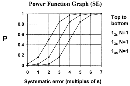 For example, the power curves for the 12s, 13s, and 14s control rules with N=1 are shown here. These are the control rules that would result if the control limits on a Levey-Jennings chart were set as the mean plus/minus 2s, 3s, or 4s. Notice that the 12s rule always gives a higher probability of rejection than the 13s or 14s rules. For systematic shifts equivalent to 2 to 4 times the standard deviation of the method, the differences of error detection are very large.
QC performance characteristics and power function graphs aren't new - they've been in the clinical chemistry literature for more than thirty years [1,2]. That's long enough for the theory to stand the test of time. Now they need to be applied to better manage the testing processes in our laboratories.
How do you use a power function graph?
The probability of false rejection (Pfr) is read from the y-intercept of a power curve. For example, as seen from the accompanying power function graph, the 12s control rule with N=1 has a Pfr of 0.05 or a 5% chance of falsely rejecting a run. The 13s and 14s control rules have Pfrs of nearly 0.00.
The probability of error detection (Ped) depends on the size of error that occurs. For example, if a systematic shift equivalent to 3 times the standard deviation of the method were medically important, the expected Ped is obtained by locating 3s on the x-axis, then reading the corresponding y-value for the power curve of interest.
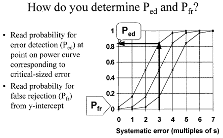 For example, the chance of detecting a 3s shift would be 16% by a 14s rule, 50% by a 13s rule, and 83% by a 12s rule. False rejections would be nearly zero for the 14s and 13s rules and approximately 5% for the 12s rule. Changing the control limits changes both error detection and false rejection of a QC procedure.
How are power curves determined?
The statistical power of a QC procedure can be determined from theory. That means you don't have to do an experiment in your laboratory to evaluate the performance of a QC procedure. The information needed can be obtained by probability calculations or by computer simulations.
For a single control rule and an N of 1, all that is needed is a table of areas under a normal curve. Estimation becomes more difficult as N increases and when multiple control rules are applied simultaneously. Mathematical skills are then needed, or alternatively, a computer simulation program can be used to generate hundreds of trial sets of data having different amounts of errors, test those data sets to see if specified control rules are violated, and estimate the proportions of runs rejected under each error condition.
By probability theory To understand the concepts of statistical power, power curves, and power function graphs, consider a simple case where N is 1 and control limits are set at the mean plus and minus 3smeas. The power curve for this QC procedure can be determined from the accompanying table, which shows the number of SDs from the mean, the area of the tail above that number of SDs (area of upper tail), and the remaining area below that number of SDs (area below tail).
| Number of SDs from mean |
Area of upper tail |
Area below upper tail |
| 0.00 | 0.5000 | 0.5000 |
| 0.50 | 0.3085 | 0.6915 |
| 1.00 | 0.1587 | 0.8413 |
| 1.50 | 0.0668 | 0.9332 |
| 1.65 | 0.0495 | 0.9505 |
| 2.00 | 0.0228 | 0.9772 |
| 2.50 | 0.0062 | 0.9938 |
| 3.00 | 0.0013 | 0.9987 |
| 3.50 | 0.0002 | 0.9998 |
| 4.00 | 0.0000 | 1.0000 |
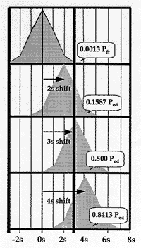
What is the probability for rejection if performance is stable? The stable distribution of expected control results is shown by the top distribution in the accompanying figure. The area of the tail that exceeds the 3s control limit is 0.0013 or a 0.13% chance of observing a control measurement or point above the upper control limit. Under stable conditions, there would be an equal chance of exceeding the lower control limit, giving a total probability of 0.0026 or 0.26% chance of a false rejection.
What is the probability for rejection if a 2s shift occurs? As shown in the second distribution from the top, the area of the tail that exceeds the control limit is now 0.1587, corresponding to a 15.87% chance of detecting a systematic error of 2s.
What is the probability for rejection if a 3s shift occurs? The mean of the third distribution is now located right at the control limit. Half of the expected values for control measurements would be above 3s, which corresponds to a 50% chance of detecting a systematic error of 3s.
Illustration of statistical power for detecting systematic shifts when using a 13s control rule and 1 control measurement per run.
What is the probability for rejection if a 4s shift occurs? The lowest distribution in the figure shows that the control limit is now located at -1s from the mean of the distribution. The area of the tail is now 0.8413, which corresponds to an 84.13% chance of deteacting a systematic error of 4s.
Similarly, for shifts of 1s, 5s, 6s, and 7s, the expected probabilities of rejection would be 0.028, 0.9772, 0.9989, and essentially 1.000, respectively.
These probabilities for rejection can be plotted versus the size of the errors, as shown here, to provide a graphical description of the performance of a 13s control rule with 1 control measurement per run. The arrows for the values of 2, 3, and 4 on the x-axis correspond to the shifts of 2s, 3s, and 4s that were shown in the previous figure. Additional points are included that correspond to shifts of 1s, 5s, 6s, and 7s.
Power curves for 12s and 14s control rules can be determined in a similar way and compared to the performance of the 13s control rule, all with Ns of 1, as shown in the earlier power function graphs. Power curves for random error can be determined in a similar way, but it's a little more complicated because the distribution expands, rather than shifts, therefore both the upper and lower tails need to be considered.
By computer simulation In practice, we have used a computer simulation program to determine many power curves [3,4]. A simulation program uses a random number generater to prepare hundreds of trial runs for specified systematic shifts of 0.0, 0.5, 1.0, 1.5, 2.0, 3.0, and 4.0 times the standard deviation and specified increases in random error that are multiples of 1.0, 1.5, 2.0, 2.5, and 3.0 times the standard deviation. For each error condition, the control results are evaluated to determine whether the control limits are exceeded, then the proportion of runs rejected is calculated to provide an estimate of the probability of rejection. These estimates are plotted versus the size of errors to provide a power function graph. For a complete description of QC performance, power curves are usually generated for both systematic and random errors, thus two power function graphs need to be prepared.
How do you read a power function graph?
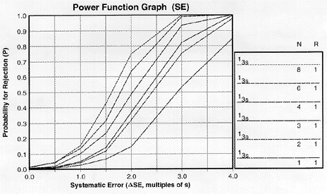 |
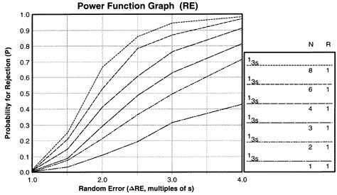
| Power function graph for detection of systematic error showing power curves for 13s control rule with Ns from 1 to 8. NOTE: Due to screen resolution and file size, the lines may appear less distinct than normal and be hard to tell apart. Therefore, as a convention here, the lines in the key from top to bottom will generally correspond to the power curves from top to bottom on the graph. Occasionally the power curves for different control rules will cross over and make it difficult to match the order in the key with the order in the graph, so you need to be careful to match the power curve with the right rule or rules. |
Let's look at a specific example. Power curves for a 13s control rule and Ns from 1 to 8 have been determined by computer simulation and stored in the QC Validator program, which was used to prepare the accompanying power function graphs.The key area at the right side of the graph identifies the control rules, number of control measurements (N), and numbers of runs (R) over which the rules are applied.
The y-axis on the power function graph shows the probability for rejection and is scaled from 0.00 to 1.00. A probability of 0.00 means there will never be a rejection; a probability of 1.00 mean there will always be a rejection. It is also common to talk about the chance of rejecting a run, which would range from 0% to 100%. The x-axis shows the size of the analytical error. For systematic error, the scale is from 0.0 to 4.0, expressed as multiplies of smeas. For example, a ![]() SE value of 2.0 corresponds to a systematic shift equivalent to 2 times the standard deviation of the measurement procedure.
SE value of 2.0 corresponds to a systematic shift equivalent to 2 times the standard deviation of the measurement procedure.
 |
| Power function graph for detection of random error showing the power curve for 13s control rule with Ns from 1 to 8. |
For random error, the y-axis again shows the probability for rejection. The x-axis shows the size of the random error from 1.0 to 4.0, again expressed as multiples of smeas.
The x-value of 1.0 represents the inherent stable imprecision of the method, which is never zero (remember the stable imprecision that is estimated by the replication experiment during method evaluation studies). A value of 2.0 corresponds to a doubling of the standard deviation of the method. The power curves for random error are not as steep as for systematic error, which suggests that random error will often be more difficult to detect than systematic error.
How do false rejection and error detection depend on control limits?
The probability of false rejection, Pfr, is given by the y-intercept of a power curve. By definition, false rejection refers to the situation where the only errors present are the errors that characterize stable performance. Stable performance is the minimum error shown on the x-axis (which is 0.0 on the SE graph or 1.0 on the RE graph), therefore the y-intercept gives the value for Pfr. For example, the power curve for the 13s rule with an N of 8 shows a Pfr of 0.01, or a 1% chance for false rejection. For lower Ns, Pfr is essentially zero.
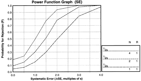 |
| Power function graph for detection of systematic error showing power curves for the 12s control rules with Ns of 1, 2, and 4. |
The power function graph for the 12s control rule with Ns from 1 to 4 shows that the false rejections vary from 5% for N=1 to 9% for N=2 and all the way to 18% for N=4. The requirement that laboratories in the U.S. must analyze at least two controls per run would lead to a 9% false rejection rate, or 9% waste of production in laboratory testing processes.
Power function graph for detection of systematic error showing power curves for the 12s control rules with Ns of 1, 2, and 4.
Therefore, with N=2 and the 12s rule, it is expected that nearly 1 out of every 10 runs would be rejected even if the measurement procedure is working properly.
Power function graphs show that error detection increases as the size of the error increases. Higher error detection is achieved by making more control measurements per run. Different control rules have different sensitivities:
- Use of narrower control limits will increase error detection.
- Adding control rules together to form multirule procedures will also increase error detection.
The exact probability of error detection, Ped, will depend on the size of errors that need to be detected. Small errors will be hard to detect; large errors will be easy to detect. To know Ped exactly, the size of the errors that are medically important need to be calculated from the quality required for the test and the imprecision and inaccuracy observed for the method.
Where can you obtain power function graphs?
In addition to the original reference sited below [2], power function graphs are available in the QC texts by Westgard and Barry [5] and Cembrowski and Carey, the OPSpecs Manual, and the EZ Rules 3 program. The EZ Rules 3 program has the most extensive library (approximately 100 power curves for different rules and Ns).
References
- Westgard JO, Groth T, Aronsson T, Falk H, deVerdier C-H. Performance characteristics of rules for internal quality control: Probabilities for false rejection and error detection. Clin Chem 1977;23:1857-67.
- Westgard JO, Groth T. Power functions for statistical control rules. Clin Chem 1979;25:863-69.
- Groth T, Falk H, Westgard JO. An interactive computer simulation program for the design of statistical control procedures in clinical chemistry. Computer Programs in Biomedicine 1981;13:73-86.
- Westgard JO, Groth T. Design and evaluation of statistical control procedures: Applications of a computer 'QC Simulator' program. Clin Chem 1981;27:1536-1545.
- Westgard JO, Barry PL. Cost-Effective Quality Control: Managing the quality and productivity of analytical processes. Washington DC, AACC Press, 1986.
- Cembrowski GS, Carey RN. Laboratory Quality Management. Chicago, ASCP Press, 1989.